“LEGO-旋转编码器”的版本间的差异
来自YFRobotwiki
| (未显示1个用户的10个中间版本) | |||
| 第7行: | 第7行: | ||
LEGO旋转编码器具有统一的兼容乐高积木的外壳,可轻松完成乐高积木的拼接,实现创意设计。 | LEGO旋转编码器具有统一的兼容乐高积木的外壳,可轻松完成乐高积木的拼接,实现创意设计。 | ||
| − | |||
| − | |||
'''扩展阅读''' | '''扩展阅读''' | ||
| + | |||
| + | EC11旋转编码器是一种增量编码器,特点:可以规避信号抖动引起的误差; | ||
增量编码器是一种将旋转位移转换为一连串数字脉冲信号的旋转式传感器。这些脉冲用来控制角位移。在Eltra编码器中角位移的转换采用了光电扫描原理。读数系统以由交替的透光窗口和不透光窗口构成的径向分度盘(码盘)的旋转为依据,同时被一个红外光源垂直照射,光把码盘的图像投射到接收器表面上。接收器覆盖着一层衍射光栅,它具有和码盘相同的窗口宽度。接收器的工作是感受光盘转动所产生的变化,然后将光变化转换成相应的电变化。再使低电平信号上升到较高电平,并产生没有任何干扰的方形脉冲,这就必须用电子电路来处理。读数系统通常采用差分方式,即将两个波形一样但相位差为180°的不同信号进行比较,以便提高输出信号的质量和稳定性。读数是再两个信号的差别基础上形成的,从而消除了干扰。 | 增量编码器是一种将旋转位移转换为一连串数字脉冲信号的旋转式传感器。这些脉冲用来控制角位移。在Eltra编码器中角位移的转换采用了光电扫描原理。读数系统以由交替的透光窗口和不透光窗口构成的径向分度盘(码盘)的旋转为依据,同时被一个红外光源垂直照射,光把码盘的图像投射到接收器表面上。接收器覆盖着一层衍射光栅,它具有和码盘相同的窗口宽度。接收器的工作是感受光盘转动所产生的变化,然后将光变化转换成相应的电变化。再使低电平信号上升到较高电平,并产生没有任何干扰的方形脉冲,这就必须用电子电路来处理。读数系统通常采用差分方式,即将两个波形一样但相位差为180°的不同信号进行比较,以便提高输出信号的质量和稳定性。读数是再两个信号的差别基础上形成的,从而消除了干扰。 | ||
| − | 更多 | + | 更多 编码器 参数请查看页末 --> 参考资料。 |
| + | |||
=== 规格参数 === | === 规格参数 === | ||
| 第22行: | 第23行: | ||
*一圈脉冲数:20个 | *一圈脉冲数:20个 | ||
*接口类型:PH2.0-4P | *接口类型:PH2.0-4P | ||
| − | *外形尺寸:单位mm,整体高 | + | *外形尺寸:单位mm,整体高 度23mm |
[[Image:乐高兼容模块外壳尺寸.png|400px]] | [[Image:乐高兼容模块外壳尺寸.png|400px]] | ||
| 第28行: | 第29行: | ||
=== 引脚说明 === | === 引脚说明 === | ||
| − | [[Image:LEGO旋转编码器-PINOUT.png | + | [[Image:LEGO旋转编码器-PINOUT.png|LEGO-旋转编码器-PINOUT]] |
| 第37行: | 第38行: | ||
* Arduino UNO 专用扩展板 | * Arduino UNO 专用扩展板 | ||
* 旋转编码器模块 | * 旋转编码器模块 | ||
| − | |||
* 线材 | * 线材 | ||
==== 电路连接示意图 ==== | ==== 电路连接示意图 ==== | ||
| − | '''旋转编码器'''的 G、V | + | '''旋转编码器'''的 G、V 、A、B 分别连接 '''Arduino UNO'''的GND、VCC 、D9、D10 引脚。 |
| − | + | [[Image:LEGO-旋转编码器-连接示意图.png|600px|连接示意图]] | |
| − | + | ||
| − | [[Image:LEGO-旋转编码器-连接示意图. | + | |
{| border="0" cellpadding="5" width="100%" | {| border="0" cellpadding="5" width="100%" | ||
| 第56行: | 第54行: | ||
<source lang="c"> | <source lang="c"> | ||
/* | /* | ||
| − | + | Read Quadrature Encoder | |
| − | - | + | - 旋钮编码 器 测试 |
This example code is in the public domain. | This example code is in the public domain. | ||
| 第65行: | 第63行: | ||
*/ | */ | ||
| − | + | /*** 顺时针 位置增加 逆时针 位置减小 ***/ | |
| − | + | #define encoderPinA 9 // A相 | |
| + | #define encoderPinB 10 // B相 | ||
| + | |||
| + | int encoderPos = 0; | ||
| + | int encoderPinALast = HIGH; | ||
| + | int encoderPinANow = HIGH; | ||
| + | |||
| + | int encoderPinBLast = HIGH; | ||
| + | int encoderPinBNow = HIGH; | ||
void setup() { | void setup() { | ||
| − | pinMode( | + | pinMode(encoderPinA, INPUT); |
| − | pinMode( | + | pinMode(encoderPinB, INPUT); |
| + | Serial.begin (115200); | ||
} | } | ||
void loop() { | void loop() { | ||
| − | if (digitalRead( | + | encoderPinANow = digitalRead(encoderPinA); |
| − | + | encoderPinBNow = digitalRead(encoderPinB); | |
| − | + | ||
| − | + | if (encoderPinALast != encoderPinANow) { | |
| + | Serial.print("A-Now:"); | ||
| + | Serial.print(encoderPinANow); | ||
| + | Serial.print("\tB-Now:"); | ||
| + | Serial.print(encoderPinBNow); | ||
| + | Serial.println(); | ||
| + | } | ||
| + | encoderPinBNow = digitalRead(encoderPinB); | ||
| + | if (encoderPinBLast != encoderPinBNow) { | ||
| + | Serial.print("A-Now:"); | ||
| + | Serial.print(encoderPinANow); | ||
| + | Serial.print("\tB-Now:"); | ||
| + | Serial.print(encoderPinBNow); | ||
| + | Serial.println(); | ||
| + | } | ||
| + | |||
| + | if ((encoderPinALast == LOW) && (encoderPinANow == HIGH)) { //A相 上升沿 | ||
| + | if (encoderPinBNow == LOW) { // B相 低电平 状态 | ||
| + | encoderPos++; | ||
| + | Serial.print("CW \t"); | ||
| + | } else { | ||
| + | encoderPos--; | ||
| + | Serial.print("CCW \t"); | ||
| + | } | ||
| + | Serial.println(encoderPos); | ||
} | } | ||
| + | |||
| + | encoderPinALast = encoderPinANow; | ||
| + | encoderPinBLast = encoderPinBNow; | ||
} | } | ||
</source> | </source> | ||
| 第103行: | 第137行: | ||
===='''程序运行结果'''==== | ===='''程序运行结果'''==== | ||
| − | + | 旋转编码器, 串口输出: | |
| + | |||
| + | [[Image:LEGO-旋转编码 器-串口输出.png|LEGO-旋转编码 器-串口输出]] | ||
| + | |||
===参考资料=== | ===参考资料=== | ||
2021年5月25日 (二) 17:02的最后版本
目录
产品简介
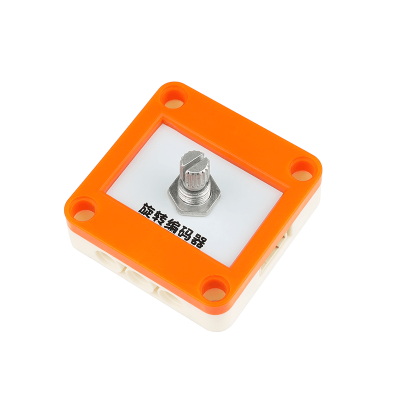
LEGO旋转编码器采用EC11旋转编码器设计制作,通过旋转可计数正反向转动输出的脉冲数;不同于电位器,旋转编码器没有角度限制。
LEGO旋转编码器具有统一的兼容乐高积木的外壳,可轻松完成乐高积木的拼接,实现创意设计。
扩展阅读
EC11旋转编码器是一种增量编码器,特点:可以规避信号抖动引起的误差;
增量编码器是一种将旋转位移转换为一连串数字脉冲信号的旋转式传感器。这些脉冲用来控制角位移。在Eltra编码器中角位移的转换采用了光电扫描原理。读数系统以由交替的透光窗口和不透光窗口构成的径向分度盘(码盘)的旋转为依据,同时被一个红外光源垂直照射,光把码盘的图像投射到接收器表面上。接收器覆盖着一层衍射光栅,它具有和码盘相同的窗口宽度。接收器的工作是感受光盘转动所产生的变化,然后将光变化转换成相应的电变化。再使低电平信号上升到较高电平,并产生没有任何干扰的方形脉冲,这就必须用电子电路来处理。读数系统通常采用差分方式,即将两个波形一样但相位差为180°的不同信号进行比较,以便提高输出信号的质量和稳定性。读数是再两个信号的差别基础上形成的,从而消除了干扰。
更多编码器参数请查看页末 --> 参考资料。
规格参数
- 供电电压:DC3.3V~5V
- 信号类型:数字输入
- 一圈脉冲数:20个
- 接口类型:PH2.0-4P
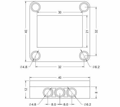
- 外形尺寸:单位mm,整体高度23mm
引脚说明
应用示例
示例需要硬件:
- Arduino UNO
- Arduino UNO 专用扩展板
- 旋转编码器模块
- 线材
电路连接示意图
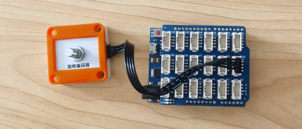
旋转编码器的 G、V、A、B分别连接 Arduino UNO的GND、VCC、D9、D10引脚。
Arduino IDE示例代码复制代码至Arduino IDE中编译上传 /* Read Quadrature Encoder - 旋钮编码器测试 This example code is in the public domain. Author : YFROBOT ZL Website : www.yfrobot.com.cn Create Time: 2021-02-19 */ /*** 顺时针 位置增加 逆时针 位置减小 ***/ #define encoderPinA 9 // A相 #define encoderPinB 10 // B相 int encoderPos = 0; int encoderPinALast = HIGH; int encoderPinANow = HIGH; int encoderPinBLast = HIGH; int encoderPinBNow = HIGH; void setup() { pinMode(encoderPinA, INPUT); pinMode(encoderPinB, INPUT); Serial.begin (115200); } void loop() { encoderPinANow = digitalRead(encoderPinA); encoderPinBNow = digitalRead(encoderPinB); if (encoderPinALast != encoderPinANow) { Serial.print("A-Now:"); Serial.print(encoderPinANow); Serial.print("\tB-Now:"); Serial.print(encoderPinBNow); Serial.println(); } encoderPinBNow = digitalRead(encoderPinB); if (encoderPinBLast != encoderPinBNow) { Serial.print("A-Now:"); Serial.print(encoderPinANow); Serial.print("\tB-Now:"); Serial.print(encoderPinBNow); Serial.println(); } if ((encoderPinALast == LOW) && (encoderPinANow == HIGH)) { //A相 上升沿 if (encoderPinBNow == LOW) { // B相 低电平 状态 encoderPos++; Serial.print("CW \t"); } else { encoderPos--; Serial.print("CCW \t"); } Serial.println(encoderPos); } encoderPinALast = encoderPinANow; encoderPinBLast = encoderPinBNow; } |
Mixly示例代码
|
Mind+示例代码Mind+ 1.7 |
程序运行结果
旋转编码器,串口输出:
参考资料
| 访问YFRobot论坛 | 论坛邀请码获取 | 技术交流群 |
| 淘宝企业店 | 淘宝直营店 | 联系我们 |


